


Ground Fault Systems
Designers and manufacturers of Residual Current Devices (RCD) for Ground Fault Protection and Earth Leakage Detection
Social media links


Link to UL page for all c-UL-us certified products


DGF5 Family
DGF5-1
24– 48 V AC or DC Control Voltage.
For 45 - 450 Hz power systems.
Internal current sensor: 28 mm with 500:1 ratio.
Delay and trip point can be factory set between 20 ms - 3 s and 30 mA - 10 A.
Operating mode: Pulsed Trip/Auto Reset.
c-UL-us certified.
External Test pushbutton.
Voltage free, form 'A' (2-connections) NO contact set.
Connection type: Wires.

DGF5-2
24– 48 V AC or DC Control Voltage.
For 45 - 450 Hz power systems.
Internal current sensor: 28 mm with 500:1 ratio.
Delay and trip point can be factory set between 20 ms - 3 s and 30 mA - 10 A.
Operating mode: Pulsed Trip/Auto Reset.
c-UL-us certified.
External Test pushbutton.
Voltage free, form 'C' (3-connections) change-over NO-C-NC contact set.
Connection type: Wires.

DGF5-3
24– 48 V AC or DC Control Voltage.
For 45 - 450 Hz power systems.
Internal current sensor: 28 mm with 500:1 ratio.
Delay and trip point can be factory set between 20 ms - 3 s and 30 mA - 10 A.
Operating mode: Pulsed Trip/Auto Reset.
c-UL-us certified.
External Test pushbutton.
Voltage free, form 'C' (3-connections) change-over NO-C-NC contact set.
Connection type: Pull-apart terminal block.

DGF5-7
Pull apart connector.
Powersupply: 24-240V AC-DC.
Internal current sensor: 28 mm with 500:1 ratio.
External test button.
Fixed factory programmed trip current 500 mA.
Fixed factory programmed delay time 500 ms.
Trip current and delay time can be customized.
Operating mode: Pulsed Trip/Auto Reset.
Voltage free, form 'Z' (4-connections) isolated NO and NC contact sets.
1 led.
Aluminium profile for horizontal mounting on DIN rail.
c-UL-us certified.

DGF7 Family
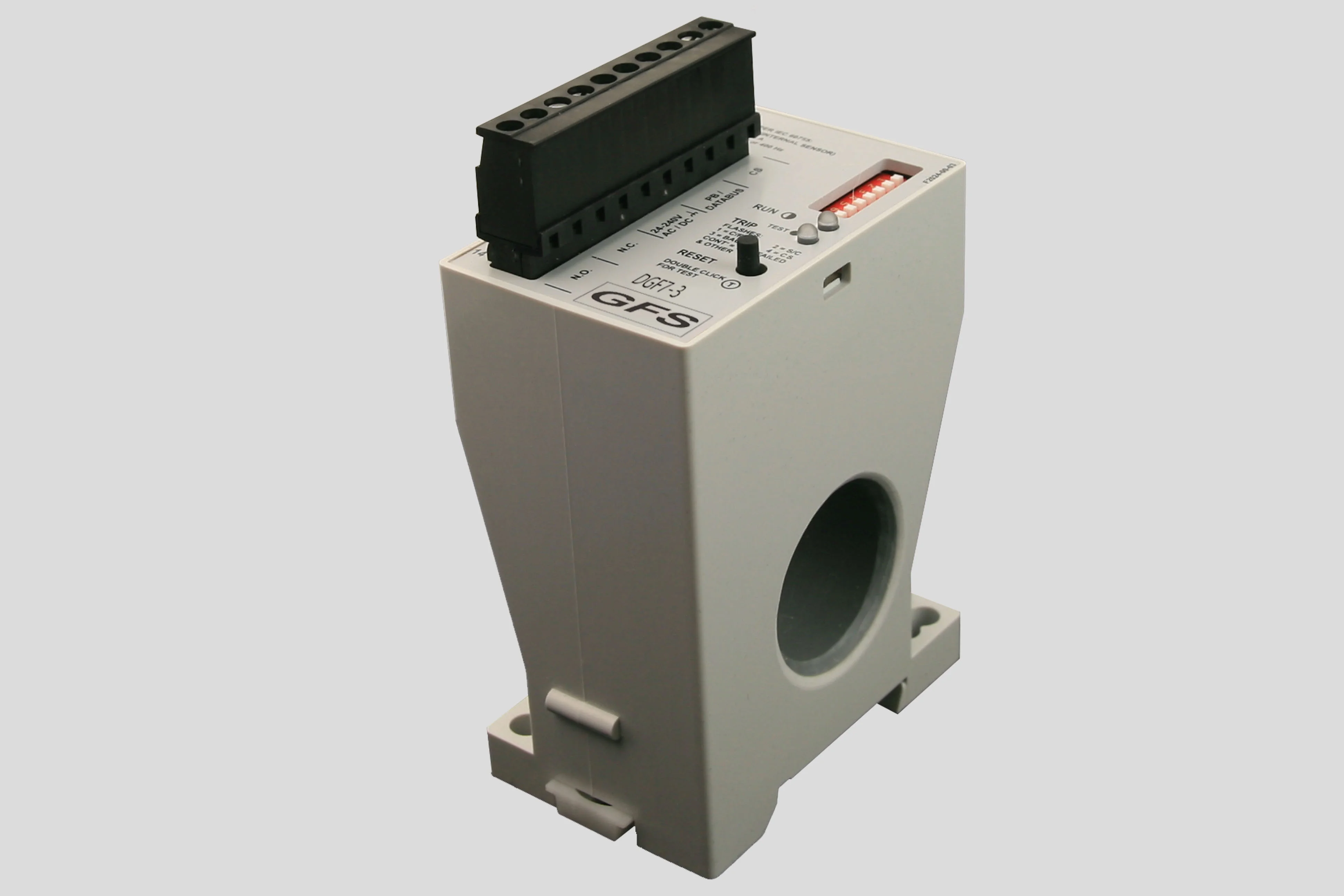
DGF7-3
24 – 240 V AC or DC Control Voltage.
For 45 - 450 Hz power systems.
Internal current sensor: 28 mm with 500:1 ratio.
External CS connection supervision: Detects a
shorted or open connection of the wires to the CS.Trip Inhibit function.
Trip current: 30 - 60 - 100 - 250 - 370 - 500 mA - 1 - 3 A.
Trip delay times:
Operating modes: Continuous Non-Failsafe, Continuous Failsafe, Pulsed Non-Failsafe, Pulsed Failsafe.
Tamper proof dipswitches.
c-UL-us certified.
2 LEDs.
Voltage free, form 'Z' (4-connections) isolated NO and NC contact sets.
Memory after loss of Control Voltage.
Built-in Reset/Test pushbutton.
Optional: external current sensor, remote reset button and DGF7 Display.
with or without Trip Inhibit 20, 100, 300 ms.
without Trip Inhibit 1000, 3000 ms.
DGF7-14
24 – 240 V AC or DC Control Voltage.
For 45 - 450 Hz power systems.
Internal current sensor: 28 mm with 500:1 ratio.
Trip current: 1, 1,5, 2, 2,5, 4, 6, 8, 10 A.
Trip delay times: 500, 1000, 1500, 2000, 2500, 5000, 7500, 10.000 ms.
Operating modes: Continuous Non-Failsafe, Continuous Failsafe, Pulsed auto reset, Pulsed Non-Failsafe.
c-UL-us certified.
1 LED.
Voltage free, form 'Z' (4-connections) isolated NO and NC contact sets.
Output for remote metering (0 - 10 V, ground fault read-out proportional to Trip level).
Aluminium profile for horizontal mounting on DIN rail.
Optional: external current sensor, remote reset/test button, remote voltmeter.

DGF7-18
24 – 240 V AC or DC Control Voltage.
For 45 - 450 Hz power systems.
Internal current sensor: 28 mm with 500:1 ratio.
Trip current: 30, 120, 210, 300, 600mA 2,4, 4,2, 6 A.
Trip delay times: 20, 500 ms.
Operating modes: Continuous Non-Failsafe, Pulsed Trip/Auto Reset.
1 LED.
Voltage free, form 'Z' (4-connections) isolated NO and NC contact sets.
c-UL-us certified.
Optional: external current sensor, external test/reset button.

DGF7-30
24 – 240 V AC or DC Control Voltage.
For 45 - 450 Hz power systems.
External CS connection supervision: Detects a shorted or open connection of the wires to the CS. Active in Series C, inactive in Series D.
Trip Inhibit function.
Trip current: 30, 100, 500 mA 1, 2, 3, 5, 9 A.
Trip delay times:
Operating modes: Continuous Non-Failsafe, Continuous Failsafe, Pulsed Non-Failsafe, Pulsed Failsafe.
Tamper proof dipswitches.
c-UL-us certified.
2 LEDs.
Voltage free, form 'Z' (4-connections) isolated NO and NC contact sets.
Memory after loss of Control Voltage.
Built-in Reset/Test pushbutton.
Requires a CS series external current sensor.
with or without Trip Inhibit 20, 300 ms.
without Trip Inhibit 1000, 3000, 10.000 ms.

DGF7-61
24 – 240 V AC or DC Control Voltage.
For 45 - 450 Hz power systems.
Internal current sensor: 28 mm with 500:1 ratio.
Trip Inhibit function.
Trip current: 30, 60, 100, 250, 370, 500 mA 1, 3 A.
Trip delay times:
Operating modes: Continuous Non-Failsafe, Continuous Failsafe, Pulsed Non-Failsafe, Pulsed Failsafe.
Tamper proof dipswitches.
c-UL-us certified.
2 LEDs.
Voltage free, form 'Z' (4-connections) isolated NO and NC contact sets.
Built-in Reset/Test pushbutton.
Optional: external current sensor, remote reset button and DGF7 Display.
with or without Trip Inhibit 20, 100, 300 ms.
without Trip Inhibit 1000, 3000 ms.

DGF7-61-JM(1)
24 – 240 V AC or DC Control Voltage.
For 45 - 450 Hz power systems.
Internal current sensor: 28 mm with 500:1 ratio.
Trip current: 30 mA.
Trip delay: 20 ms without trip inhibit.
Operating mode:
Internal test/reset button.
2 LEDs.
Voltage free, form 'Z' (4-connections) isolated NO and NC contact sets.
c-UL-us certified.
Optional: display, external current sensor, external reset button.
DGF7-61-JM: Continuous Non-Failsafe operation.
DGF7-61-JM1: Continuous Failsafe operation.

DGF7-Display
Compatible with DGF7-3, DGF7-61, DGF7-61-JM and DGF7-61-JM1.
Door mounted operator interface.
Four digit LCD panel.
Shows actual G/F current in relative or absolute mode.
Auto ranging.
Refreshes every 0,5 seconds.
Shows current G/F Trip Level setting.
Indicates cause of trip using codes.
Memory after loss of Control Voltage.
Ability to test and reset the connected unit.
Ability to test the LCD panel.
Actual current reading can be adjusted according to the connected CS ratio.
Connected by a single twisted pair of wires.

Other units
DGF100
24 – 240 V AC or DC Control Voltage.
For 45 - 450 Hz power systems.
Internal current sensor: 46 mm with 500:1 ratio.
Trip current: 30 - 40 - 60 - 90 - 150 - 250 - 400 - 600 - 900 mA - 1,5 - 2,5 - 4 - 6 - 9 A.
Trip delay times: 20 - 50 - 100 - 200 - 500 ms - 1 - 2 - 5 s.
Operating modes: Continuous Non-Failsafe, Continuous Failsafe, Pulsed Auto Reset, Pulsed Non-Failsafe.
Internal test/reset button.
2 LEDS.
Voltage free, form 'Z' (4-connections) isolated NO and NC contact sets.
c-UL-us certified.
Optional: display, external current sensor, external reset button.

DGF100 Display
Compatible with DGF100.
Door mounted operator interface.
Four digit LCD panel.
2 LEDs.
Shows actual G/F current.
Auto ranging.
Trip memory after loss of Control Voltage.
Ability to reset the DGF100.
Ability to test the DGF100, this mode can be enabled/disabled.
Ability to test the LCD panel.
Connected by a RJ-10 type connector with 4-wire telephone cable (1 m cable included).

GFU20
120 – 240 V AC or DC Control Voltage.
For 45 - 450 Hz power systems.
External CS connection supervision: Detects a shorted or open connection of the wires to the CS.
Trip Inhibit function.
Trip current for CS5-types sensors: 2,5 A - 60 A in 25 steps.
Trip current for CS100-types sensors: 50 A - 1200 A in 25 steps.
Trip delay times: 25, 65, 100, 130, 160, 190, 225, 255, 375, 500, 625, 750, 875, 1000 ms.
Operating modes: Non-Failsafe and Failsafe.
Internal test/reset button.
2 LEDS.
Memory after loss of Control Voltage.
Internal voltage-operated tripping device, form ‘C’ (3 connections) change-over NO-C-NC contact set, with an external toggle handle
c-UL-us certified.
Requires a CS series external current sensor.

LIM2
Isolated 24 – 240 V AC or DC Control Voltage.
For 380V to 600V and 45 - 450 Hz power systems.
Maximum primary let-through current : 20, 35 or 50 mA RMS.
Trip setting potentiometer adjustable from 20 to 80% of let-through current.
Trip operating modes:
Failsafe operation.
Non-Failsafe operation RRPL (Relay Release at Power Loss).
Non-Failsafe operation Latched.
Alarm setting potentiometer adjustable from 20 to 80% of let-through current.
Alarm operating modes:
Failsafe operation.
Non-Failsafe operation RRPL (Relay Release at Power Loss).
Non-Failsafe operation Latched.
Internal test/reset button.
6 LEDS: 3 LEDs for functionality and 3 LEDs for locating the affected phase.
2 voltage free, form 'Z' (4-connections) isolated NO and NC contact sets.

Current Sensors
Round Sensors
External current sensor with 28 mm window
| 500 :1 |External current sensor with 50 mm window
| 500 :1 |External current sensor with 65 mm window
| 500 :1 |External current sensor with 90 mm window
| 500 :1 |External current sensor with 95 mm window
External current sensor with 144 mm window
External current sensor with 150 mm window
| 500 :1 |External current sensor with 240 mm window
| 500 :1 | 1000 :1 | 2000 :1 | 10000 :1 |

Square Sensors
External current sensor with 150 x 170 mm window
| 500 :1 |External current sensor with 100 x 250 mm window
| 500 :1 | 1000 :1 | 2000 :1 |External current sensor with 100 x 350 mm window
| 500 :1 | 1000 :1 | 2000 :1 |

Top Hat Sensors
External current sensor with 300 x 300 mm window
| 500 :1 |External current sensor with 200 x 286 mm window
| 500 :1 | 1000 :1 | 2000 :1 | 10000 :1 |

Ground Fault Systems
Designers and manufacturers of Residual Current Devices (RCD) for Ground Fault Protection and Earth Leakage Detection
DGF5 Family
DGF5-1
24– 48 V AC or DC Control Voltage.
For 45 - 450 Hz power systems.
Internal current sensor: 28 mm with 500:1 ratio.
Delay and trip point can be factory set between 20 ms - 3 s and 30 mA - 10 A.
Operating mode: Pulsed Trip/Auto Reset.
c-UL-us certified.
External Test pushbutton.
Voltage free, form 'A' (2-connections) NO contact set.
Connection type: Wires.
DGF5-2
24– 48 V AC or DC Control Voltage.
For 45 - 450 Hz power systems.
Internal current sensor: 28 mm with 500:1 ratio.
Delay and trip point can be factory set between 20 ms - 3 s and 30 mA - 10 A.
Operating mode: Pulsed Trip/Auto Reset.
c-UL-us certified.
External Test pushbutton.
Voltage free, form 'C' (3-connections) change-over NO-C-NC contact set.
Connection type: Wires.
DGF5-3
24– 48 V AC or DC Control Voltage.
For 45 - 450 Hz power systems.
Internal current sensor: 28 mm with 500:1 ratio.
Delay and trip point can be factory set between 20 ms - 3 s and 30 mA - 10 A.
Operating mode: Pulsed Trip/Auto Reset.
c-UL-us certified.
External Test pushbutton.
Voltage free, form 'C' (3-connections) change-over NO-C-NC contact set.
Connection type: Pull-apart terminal block.
DGF5-7
Pull apart connector.
Powersupply: 24-240V AC-DC.
Internal current sensor: 28 mm with 500:1 ratio.
External test button.
Fixed factory programmed trip current 500 mA.
Fixed factory programmed delay time 500 ms.
Trip current and delay time can be customized.
Operating mode: Pulsed Trip/Auto Reset.
Voltage free, form 'Z' (4-connections) isolated NO and NC contact sets.
1 led.
Aluminium profile for horizontal mounting on DIN rail.
c-UL-us certified.
DGF7 Family
DGF7-3
24 – 240 V AC or DC Control Voltage.
For 45 - 450 Hz power systems.
Internal current sensor: 28 mm with 500:1 ratio.
External CS connection supervision: Detects a
shorted or open connection of the wires to the CS.Trip Inhibit function.
Trip current: 30 - 60 - 100 - 250 - 370 - 500 mA - 1 - 3 A.
Trip delay times:
Operating modes: Continuous Non-Failsafe, Continuous Failsafe, Pulsed Non-Failsafe, Pulsed Failsafe.
Tamper proof dipswitches.
c-UL-us certified.
2 LEDs.
Voltage free, form 'Z' (4-connections) isolated NO and NC contact sets.
Memory after loss of Control Voltage.
Built-in Reset/Test pushbutton.
Optional: external current sensor, remote reset button and DGF7 Display.
with or without Trip Inhibit 20, 100, 300 ms.
without Trip Inhibit 1000, 3000 ms.
DGF7-14
24 – 240 V AC or DC Control Voltage.
For 45 - 450 Hz power systems.
Internal current sensor: 28 mm with 500:1 ratio.
Trip current: 1, 1,5, 2, 2,5, 4, 6, 8, 10 A.
Trip delay times: 500, 1000, 1500, 2000, 2500, 5000, 7500, 10.000 ms.
Operating modes: Continuous Non-Failsafe, Continuous Failsafe, Pulsed auto reset, Pulsed Non-Failsafe.
c-UL-us certified.
1 LED.
Voltage free, form 'Z' (4-connections) isolated NO and NC contact sets.
Output for remote metering (0 - 10 V, ground fault read-out proportional to Trip level).
Aluminium profile for horizontal mounting on DIN rail.
Optional: external current sensor, remote reset/test button, remote voltmeter.
DGF7-18
24 – 240 V AC or DC Control Voltage.
For 45 - 450 Hz power systems.
Internal current sensor: 28 mm with 500:1 ratio.
Trip current: 30, 120, 210, 300, 600mA 2,4, 4,2, 6 A.
Trip delay times: 20, 500 ms.
Operating modes: Continuous Non-Failsafe, Pulsed Trip/Auto Reset.
1 LED.
Voltage free, form 'Z' (4-connections) isolated NO and NC contact sets.
c-UL-us certified.
Optional: external current sensor, external test/reset button.
DGF7-30
24 – 240 V AC or DC Control Voltage.
For 45 - 450 Hz power systems.
External CS connection supervision: Detects a shorted or open connection of the wires to the CS. Active in Series C, inactive in Series D.
Trip Inhibit function.
Trip current: 30, 100, 500 mA 1, 2, 3, 5, 9 A.
Trip delay times:
Operating modes: Continuous Non-Failsafe, Continuous Failsafe, Pulsed Non-Failsafe, Pulsed Failsafe.
Tamper proof dipswitches.
c-UL-us certified.
2 LEDs.
Voltage free, form 'Z' (4-connections) isolated NO and NC contact sets.
Memory after loss of Control Voltage.
Built-in Reset/Test pushbutton.
Requires a CS series external current sensor.
with or without Trip Inhibit 20, 300 ms.
without Trip Inhibit 1000, 3000, 10.000 ms.
DGF7-61
24 – 240 V AC or DC Control Voltage.
For 45 - 450 Hz power systems.
Internal current sensor: 28 mm with 500:1 ratio.
Trip Inhibit function.
Trip current: 30, 60, 100, 250, 370, 500 mA 1, 3 A.
Trip delay times:
Operating modes: Continuous Non-Failsafe, Continuous Failsafe, Pulsed Non-Failsafe, Pulsed Failsafe.
Tamper proof dipswitches.
c-UL-us certified.
2 LEDs.
Voltage free, form 'Z' (4-connections) isolated NO and NC contact sets.
Built-in Reset/Test pushbutton.
Optional: external current sensor, remote reset button and DGF7 Display.
with or without Trip Inhibit 20, 100, 300 ms.
without Trip Inhibit 1000, 3000 ms.
DGF7-61-JM(1)
24 – 240 V AC or DC Control Voltage.
For 45 - 450 Hz power systems.
Internal current sensor: 28 mm with 500:1 ratio.
Trip current: 30 mA.
Trip delay: 20 ms without trip inhibit.
Operating mode:
Internal test/reset button.
2 LEDs.
Voltage free, form 'Z' (4-connections) isolated NO and NC contact sets.
c-UL-us certified.
Optional: external current sensor, remote reset button and DGF7 Display.
DGF7-61-JM: Continuous Non-Failsafe operation.
DGF7-61-JM1: Continuous Failsafe operation.
DGF7-Display
Compatible with DGF7-3, DGF7-61, DGF7-61-JM and DGF7-61-JM1.
Door mounted operator interface.
Four digit LCD panel.
Shows actual G/F current in relative or absolute mode.
Auto ranging.
Refreshes every 0,5 seconds.
Shows current G/F Trip Level setting.
Indicates cause of trip using codes.
Memory after loss of Control Voltage.
Ability to test and reset the connected unit.
Ability to test the LCD panel.
Actual current reading can be adjusted according to the connected CS ratio.
Connected by a single twisted pair of wires.
Other units
DGF100
24 – 240 V AC or DC Control Voltage.
For 45 - 450 Hz power systems.
Internal current sensor: 46 mm with 500:1 ratio.
Trip current: 30 - 40 - 60 - 90 - 150 - 250 - 400 - 600 - 900 mA - 1,5 - 2,5 - 4 - 6 - 9 A.
Trip delay times: 20 - 50 - 100 - 200 - 500 ms - 1 - 2 - 5 s.
Operating modes: Continuous Non-Failsafe, Continuous Failsafe, Pulsed Auto Reset, Pulsed Non-Failsafe.
Internal test/reset button.
2 LEDS.
Voltage free, form 'Z' (4-connections) isolated NO and NC contact sets.
c-UL-us certified.
Optional:DGF100 display, external current sensor, external reset button.
DGF100 Display
Compatible with DGF100.
Door mounted operator interface.
Four digit LCD panel.
2 LEDs.
Shows actual G/F current.
Auto ranging.
Trip memory after loss of Control Voltage.
Ability to reset the DGF100.
Ability to test the DGF100, this mode can be enabled/disabled.
Ability to test the LCD panel.
Connected by a RJ-10 type connector with 4-wire telephone cable (1 m cable included).
GFU20
120 – 240 V AC or DC Control Voltage.
For 45 - 450 Hz power systems.
External CS connection supervision: Detects a shorted or open connection of the wires to the CS.
Trip Inhibit function.
Trip current for CS5-types sensors: 2,5 A - 60 A in 25 steps.
Trip current for CS100-types sensors: 50 A - 1200 A in 25 steps.
Trip delay times: 25, 65, 100, 130, 160, 190, 225, 255, 375, 500, 625, 750, 875, 1000 ms.
Operating modes: Non-Failsafe and Failsafe.
Internal test/reset button.
2 LEDS.
Memory after loss of Control Voltage.
Internal voltage-operated tripping device, form ‘C’ (3 connections) change-over NO-C-NC contact set, with an external toggle handle
c-UL-us certified.
Requires a CS series external current sensor.
LIM
Isolated 24 – 240 V AC or DC Control Voltage.
For 380V to 600V and 45 - 450 Hz power systems.
Maximum primary let-through current : 20, 35 or 50 mA RMS.
Trip setting potentiometer adjustable from 20 to 80% of let-through current.
Trip operating modes:
Failsafe operation.
Non-Failsafe operation RRPL (Relay Release at Power Loss).
Non-Failsafe operation Latched.
Alarm setting potentiometer adjustable from 20 to 80% of let-through current.
Alarm operating modes:
Failsafe operation.
Non-Failsafe operation RRPL (Relay Release at Power Loss).
Non-Failsafe operation Latched.
Internal test/reset button.
6 LEDS: 3 LEDs for functionality and 3 LEDs for locating the affected phase.
2 voltage free, form 'Z' (4-connections) isolated NO and NC contact sets.
Current Sensors
Round Sensors
External current sensor with 28 mm window
| 500 :1 |External current sensor with 50 mm window
| 500 :1 |External current sensor with 65 mm window
| 500 :1 |External current sensor with 90 mm window
| 500 :1 |External current sensor with 95 mm window
External current sensor with 144 mm window
External current sensor with 150 mm window
| 500 :1 |External current sensor with 240 mm window
| 500 :1 | 1000 :1 | 2000 :1 | 10000 :1 |
Square Sensors
External current sensor with 150 x 170 mm window
| 500 :1 |External current sensor with 100 x 250 mm window
| 500 :1 | 1000 :1 | 2000 :1 |External current sensor with 100 x 350 mm window
| 500 :1 | 1000 :1 | 2000 :1 |
Top Hat Sensors
External current sensor with 300 x 300 mm window
| 500 :1 |External current sensor with 200 x 286 mm window
| 500 :1 | 1000 :1 | 2000 :1 | 10000 :1 |