


DGF7-3 product page
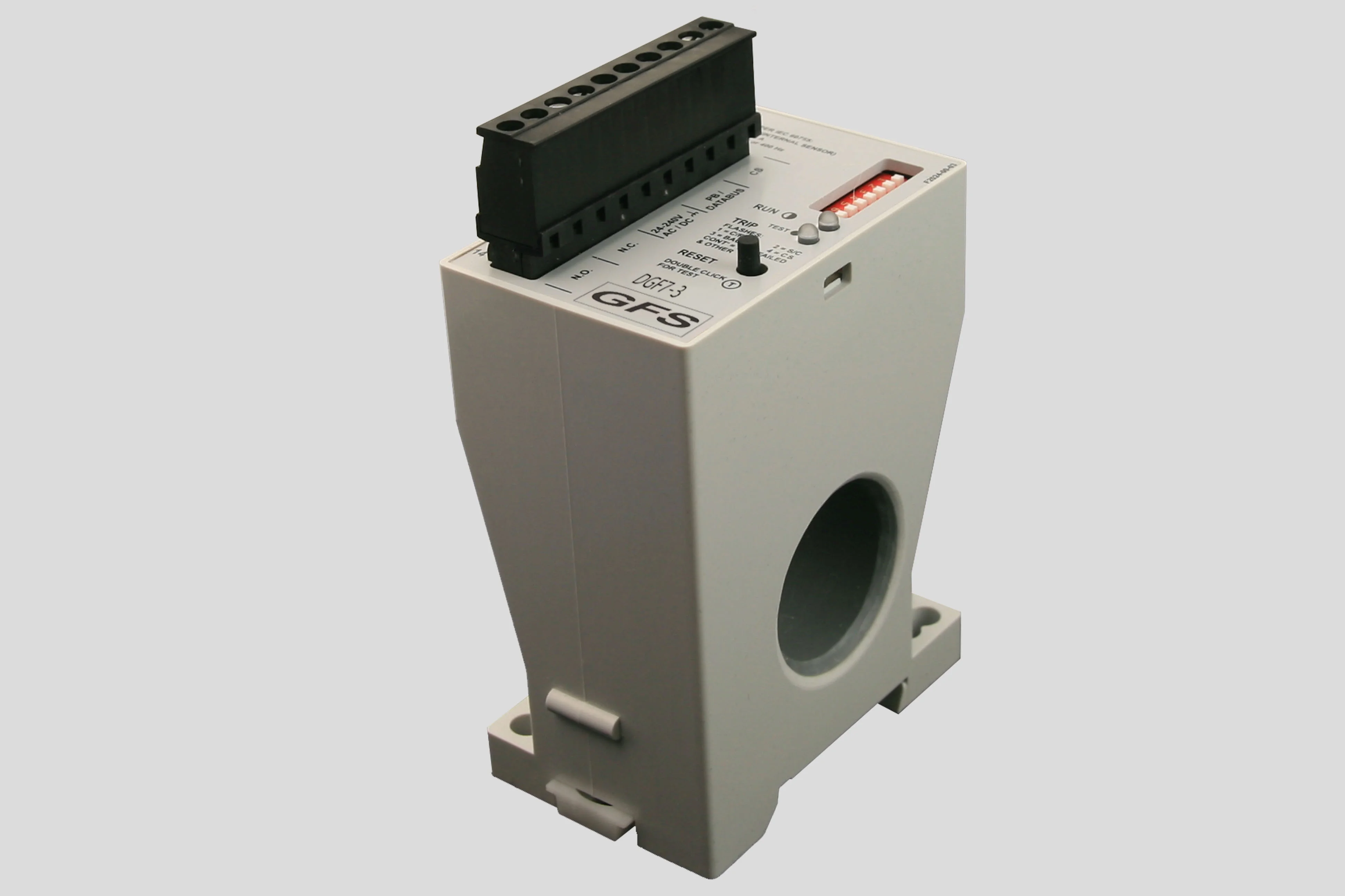


The DGF7-3 is a microprocessor based ground fault unit for use on solidly grounded or resistance grounded systems. This innovative digital electronic unit measures ground fault current using a built-in 28 mm zero sequence Current Sensor (CS), or an external CS. (Go to Sensors.)External CSs with different cable windows, round or square and split core, and various current ratios are available. Once an external CS is detected this is logged in memory and is used to detect a shorted or open connection of the wires to the CS. Both situations will call for a trip of the system, as it is unprotected from there on.
The system will react to alternating current (AC) only and will reject direct current (DC) signals. Accuracy will be maintained over a frequency range of 45 - 450 Hz, making it suitable for variable frequency drive applications. The DGF7-3 is a Class A device as defined in the IEC 60755 standard; it is therefore fully characterized for operation with sinusoidal AC and pulsating DC currents.
The maximum system operating voltage for the DGF7-3 is 660 V, when passing the system power conductors through the built-in CS. However, by using any GFS external CS and insulating the busbars, or by using any suitably rated, commercially available, interposing CT and passing the secondary lead through the built-in CS, the unit can be used on any system voltage.
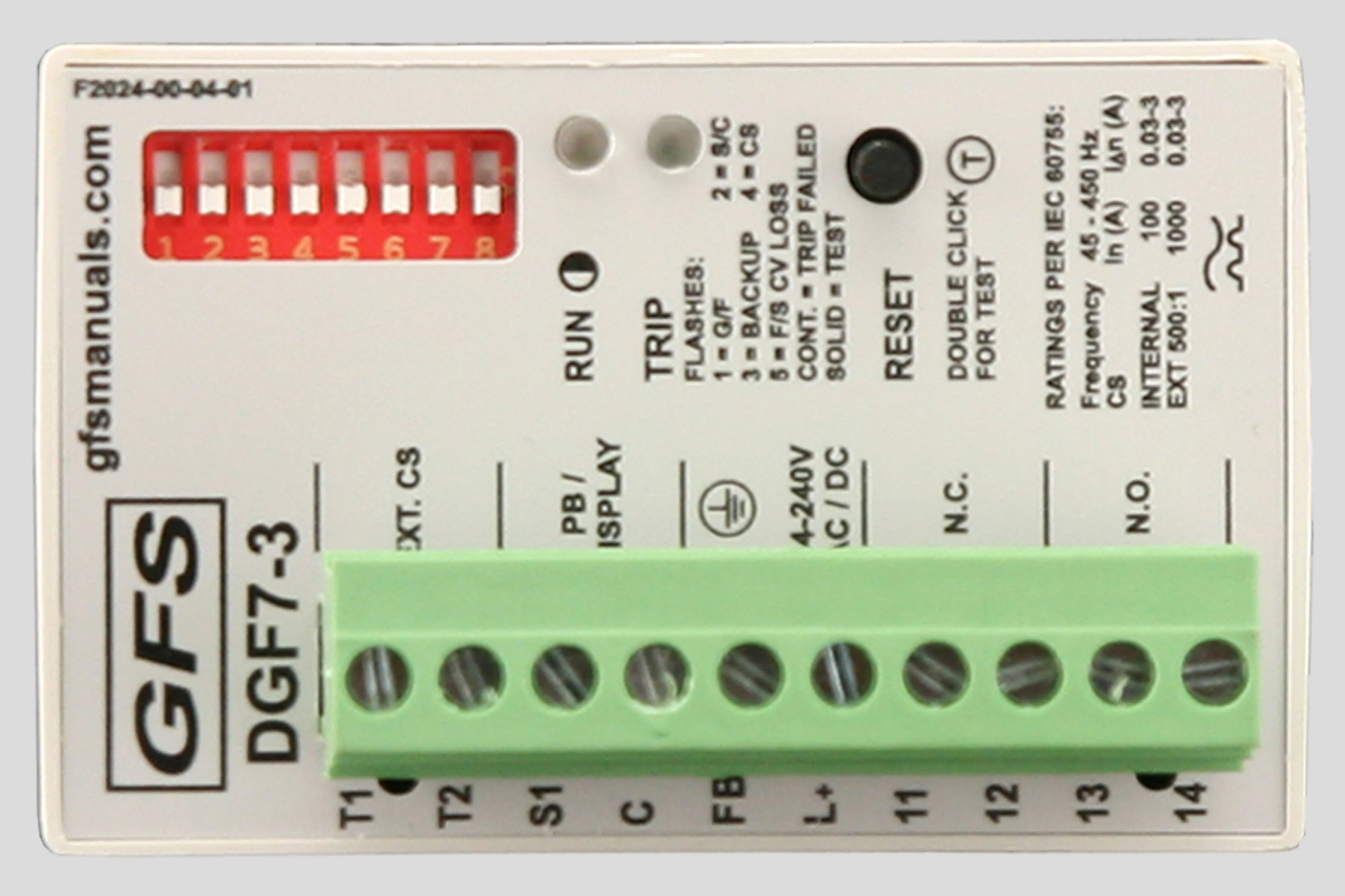
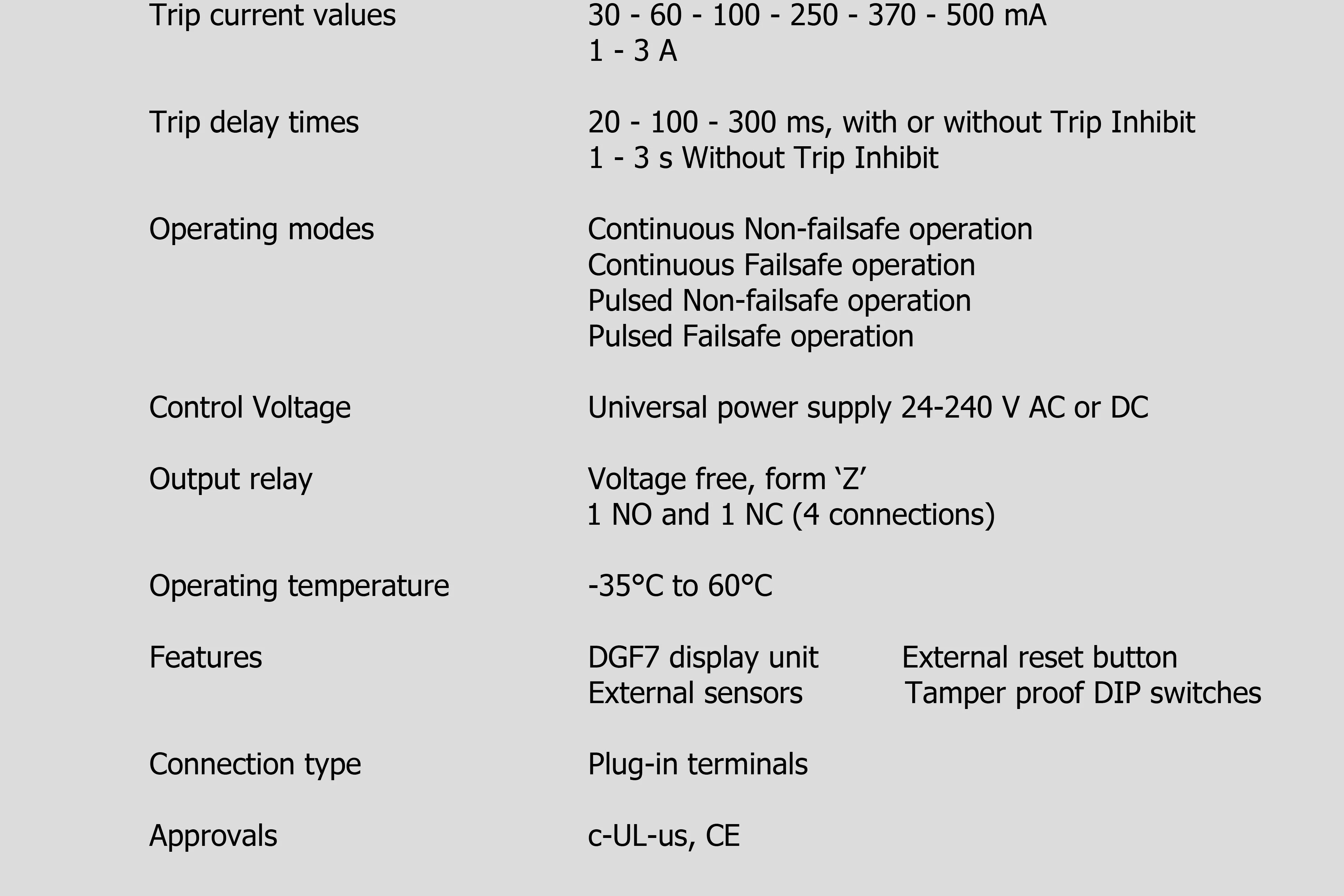
The DGF7-3 houses a non-isolated universal power supply from 24 - 240 V AC or DC and is equipped with form ‘Z’ (4 connections) isolated NO and NC contact sets to operate the upstream protection device and to indicate a failure of the system.The Ground Fault Current Trip level (30 mA – 3 A, 8 steps), Trip Delay Time (20 ms – 3 s, 5 steps), Trip Inhibit (enabled/disabled) and the Relay Operating Mode (Continuous Non-Failsafe, Continuous Failsafe, Pulsed Non-Failsafe, Pulsed Failsafe) are set on a front accessible dipswitch array.
The dipswitch array is made ‘tamper proof’, meaning that manipulating the switches will not change the settings, unless a special procedure is followed. If the procedure is not followed correctly the red and green LEDs will flash alternately, indicating an attempt to illegally change the settings. The original settings will stay valid until the entire procedure is followed.
The measured current is compared against two setpoints. The lower one is the Ground Fault (G/F) setpoint, the higher one is the High Current (H/C) setpoint. Using different ratio Current Sensors or interposing CTs will influence the setpoints. When the current exceeds the G/F setpoint during the set delay, but does not reach the H/C level, a ‘G/F’ is diagnosed and the unit trips by operating its internal relay. Should a fault be approaching a dead short to ground, causing a residual current exceeding the H/C setpoint, then without any intentional delay the unit operates its relay, indicating a Short Circuit ‘S/C’.
The user can select the operation of the relay to be ‘Trip Inhibited’. Together with an upstream tripping device (fuses or breaker) it can protect local contactor contacts in the case of H/C faults. In this case the unit does not trip initially when the measured current exceeds the H/C setpoint, but waits for the upstream device to take care of current interruption and then trips. The latter trip flags the location of the fault to the user and also allows, after inspection for welded contacts, fast re-closure of the upstream tripping device. Should the upstream device fail to perform, then automatic backup protection makes the DGF7-3 trip, as a last resort, one second after the H/C occurred. This makes it possible to design a Type 2 coordinated installation, according to the IEC 60755 standard and a Class 2, according to the UL 1053 standard.
A single press of the ‘RESET’ button, or an external, voltage free, momentary button resets the unit after a trip. A functional test of the DGF7-3 is started by either double clicking the cover mounted pushbutton, or by invoking a test on the DGF7 Display.
A green ‘RUN’ LED flashes, alternating one second on and off, to indicate that sufficient Control Voltage is applied (Power OK).
A red ‘TRIP’ LED indicates that the DGF7-3 has sensed a fault and that the output contacts have operated. The blinking sequence of the red LED indicates the type of fault. When the power to the DGF7-3 is removed, pressing the cover mounted reset button will show the green LED when no fault was there before power-down. If a fault was present before power-down, the red LED will indicate the fault by the blinking sequence.
A 10 point Pull-apart terminal block simplifies connection of field wiring.
A communications port provides access for a remote display. The remote DGF7 Display (see below) shows the actual ground fault current during normal running of the systems. After a trip the ground fault current just prior to the trip is displayed. If the DGF7 Display was connected to the DGF7-3 at the moment of a trip and the DGF7-3’s Control Voltage is turned off, pressing the ‘VERIFY’ button will show the cause of the trip.
To ensure that the DGF7-3 will function in severe circumstances, it is encapsulated in polyurethane (PUR) to make sure it is not vulnerable to mechanical shock, vibration nor weather.
DGF7 Display


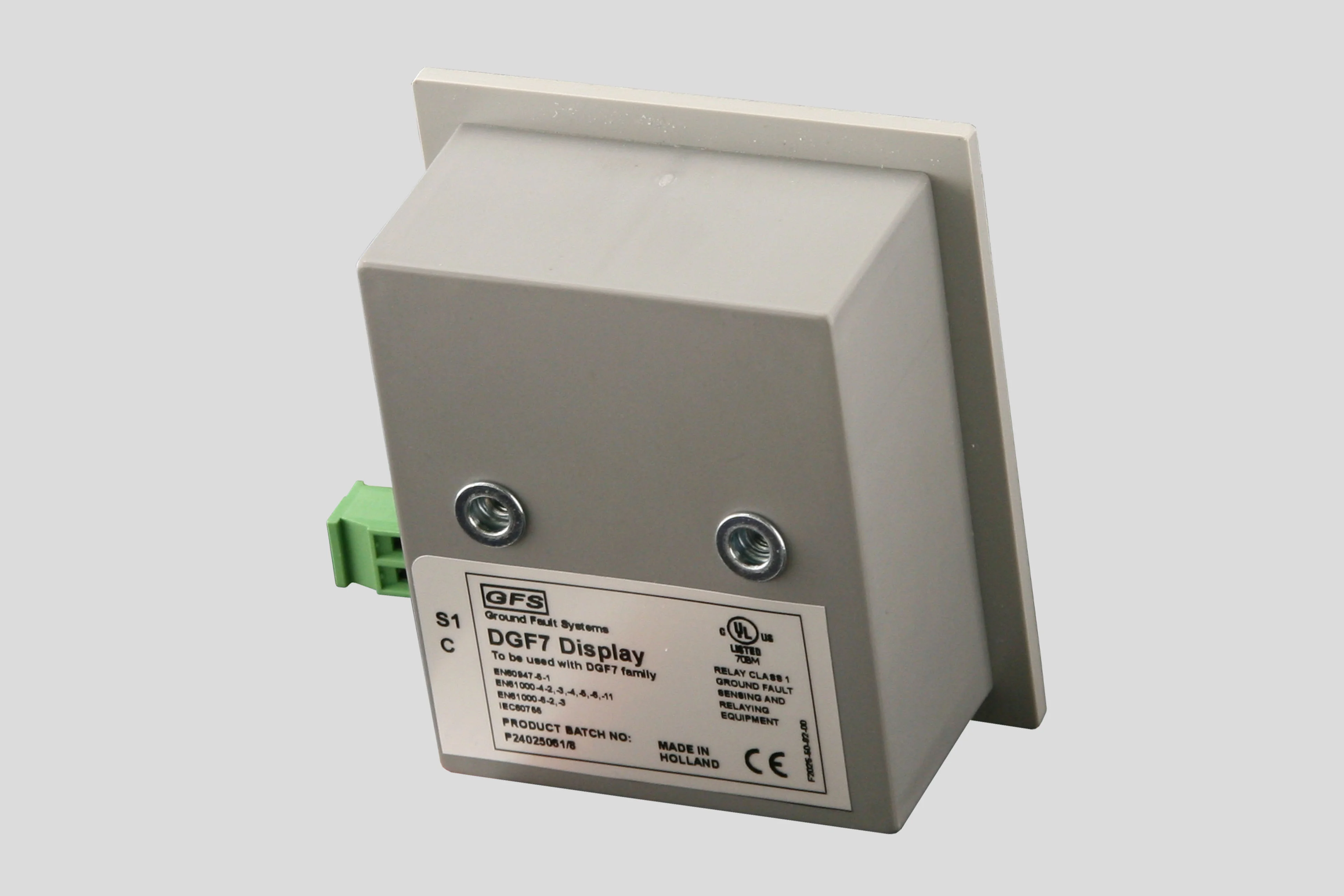

The door mounted DGF7 Display Unit is connected to the DGF7‑3/DGF7‑61 Unit by up to five meter of cable (must be shielded cable if longer than one meter). It provides the following remote indications and functions:
Continuous reading of actual, residual ground fault current in Amperes or as a percentage of the Ground Fault Trip Level, employing auto ranging.
-
'RESET' pushbutton with configurable 'Start Test' capability.
-
Display of the trip current setting, after a Test Trip has been activated.
-
'SHOW TRIP' pushbutton. Remains functional even when Control Voltage is switched off. Pressing the button will cause the LCD display to show whether or not the DGF7-3, to which it is connected, was in a tripped state at the instant of power loss. This way the user is able to verify which one of a group of units tripped their associated tripping device. This information remains accessible for at least 10 hours after power is lost.
-
Display of the pre-trip ground fault current, after a trip has occurred (flashing display).
-
Shows trip causes, after pressing 'SHOW TRIP'.
-
When the ground fault current exceeds the system's measuring range, the display shows Out meaning 'Out of range'. Depending on various internal variables, the maximum value that can be represented (whether in relative or absolute format) before resorting to the 'Out of range' indication varies from around 400 to 800% of the Ground Fault Trip Level.
-
Power over datalink, no external power supply needed.
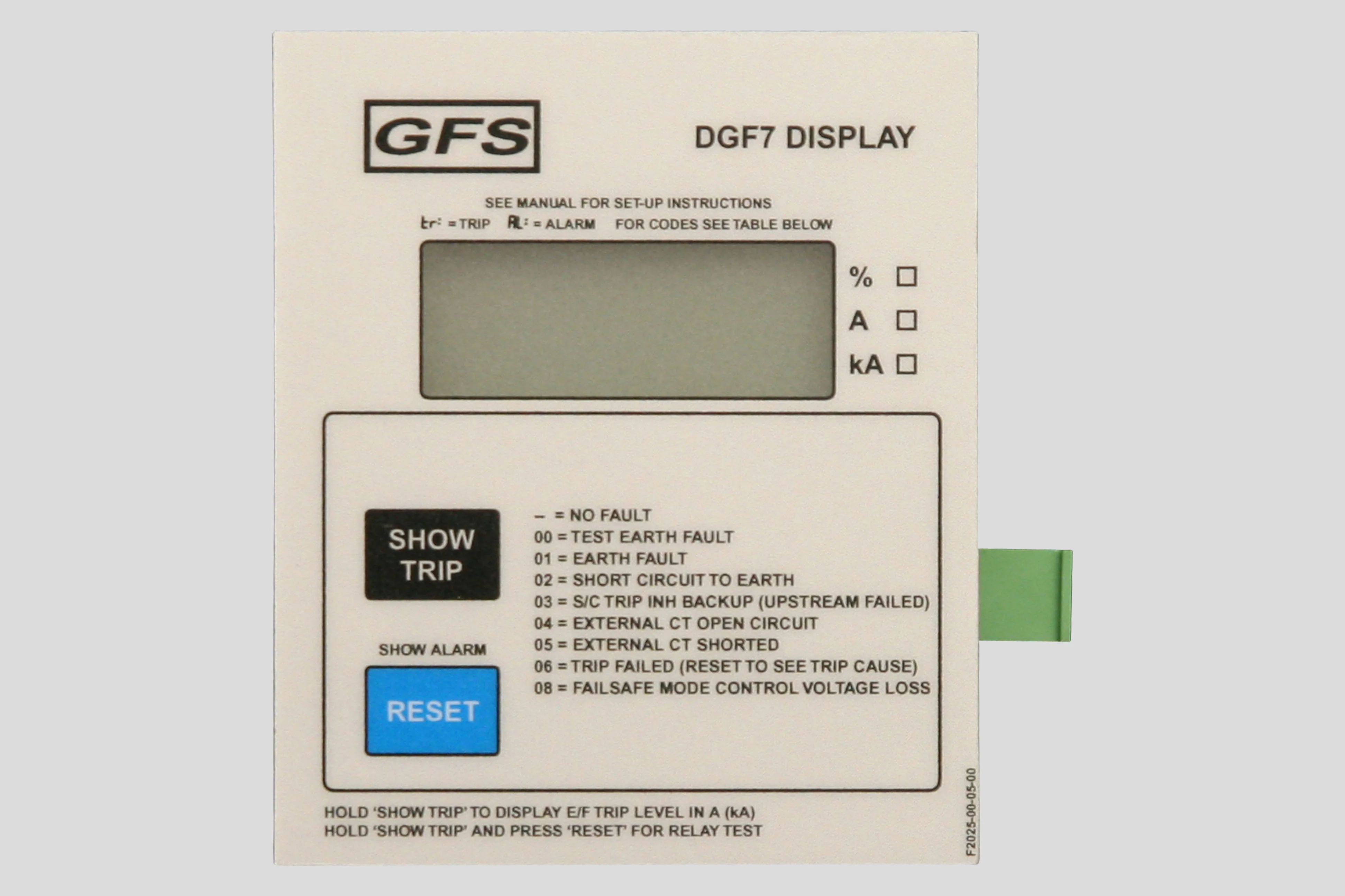
The Numerical LCD window displays actual ground fault current in percentages or in A.
3 blank boxes to the right of the LCD display window are marked '%', 'A' and 'kA'. Use a permanent marker to check the appropriate box as follows:
'%' - when using the relative format.
'A' - when using the built-in Current Sensor, an external Current Sensor, or a 500:5 ratio interposing Current Transformer.
'kA' - when using a 5000:5 ratio interposing Current Transformer.
DGF7-3 product page

The DGF7-3 is a microprocessor based ground fault unit for use on solidly grounded or resistance grounded systems. This innovative digital electronic unit measures ground fault current using a built-in 28 mm zero sequence Current Sensor (CS), or an external CS. (Go to Sensors.)External CSs with different cable windows, round or square and split core, and various current ratios are available. Once an external CS is detected this is logged in memory and is used to detect a shorted or open connection of the wires to the CS. Both situations will call for a trip of the system, as it is unprotected from there on.
The system will react to alternating current (AC) only and will reject direct current (DC) signals. Accuracy will be maintained over a frequency range of 45 - 450 Hz, making it suitable for variable frequency drive applications. The DGF7-3 is a Class A device as defined in the IEC 60755 standard; it is therefore fully characterized for operation with sinusoidal AC and pulsating DC currents.
The maximum system operating voltage for the DGF7-3 is 660 V, when passing the system power conductors through the built-in CS. However, by using any GFS external CS and insulating the busbars, or by using any suitably rated, commercially available, interposing CT and passing the secondary lead through the built-in CS, the unit can be used on any system voltage.
The DGF7-3 houses a non-isolated universal power supply from 24 - 240 V AC or DC and is equipped with form ‘Z’ (4 connections) isolated NO and NC contact sets to operate the upstream protection device and to indicate a failure of the system.The Ground Fault Current Trip level (30 mA – 3 A, 8 steps), Trip Delay Time (20 ms – 3 s, 5 steps), Trip Inhibit (enabled/disabled) and the Relay Operating Mode (Continuous Non-Failsafe, Continuous Failsafe, Pulsed Non-Failsafe, Pulsed Failsafe) are set on a front accessible dipswitch array.
The dipswitch array is made ‘tamper proof’, meaning that manipulating the switches will not change the settings, unless a special procedure is followed. If the procedure is not followed correctly the red and green LEDs will flash alternately, indicating an attempt to illegally change the settings. The original settings will stay valid until the entire procedure is followed.
The measured current is compared against two setpoints. The lower one is the Ground Fault (G/F) setpoint, the higher one is the High Current (H/C) setpoint. Using different ratio Current Sensors or interposing CTs will influence the setpoints. When the current exceeds the G/F setpoint during the set delay, but does not reach the H/C level, a ‘G/F’ is diagnosed and the unit trips by operating its internal relay. Should a fault be approaching a dead short to ground, causing a residual current exceeding the H/C setpoint, then without any intentional delay the unit operates its relay, indicating a Short Circuit ‘S/C’.
The user can select the operation of the relay to be ‘Trip Inhibited’. Together with an upstream tripping device (fuses or breaker) it can protect local contactor contacts in the case of H/C faults. In this case the unit does not trip initially when the measured current exceeds the H/C setpoint, but waits for the upstream device to take care of current interruption and then trips. The latter trip flags the location of the fault to the user and also allows, after inspection for welded contacts, fast re-closure of the upstream tripping device. Should the upstream device fail to perform, then automatic backup protection makes the DGF7-3 trip, as a last resort, one second after the H/C occurred. This makes it possible to design a Type 2 coordinated installation, according to the IEC 60755 standard and a Class 2, according to the UL 1053 standard.
A single press of the ‘RESET’ button, or an external, voltage free, momentary button resets the unit after a trip. A functional test of the DGF7-3 is started by either double clicking the cover mounted pushbutton, or by invoking a test on the DGF7 Display.
A green ‘RUN’ LED flashes, alternating one second on and off, to indicate that sufficient Control Voltage is applied (Power OK).
A red ‘TRIP’ LED indicates that the DGF7-3 has sensed a fault and that the output contacts have operated. The blinking sequence of the red LED indicates the type of fault. When the power to the DGF7-3 is removed, pressing the cover mounted reset button will show the green LED when no fault was there before power-down. If a fault was present before power-down, the red LED will indicate the fault by the blinking sequence. The fault can only be reset when Control Voltage is present.
A 10 point Pull-apart terminal block simplifies connection of field wiring.
A communications port provides access for a remote display. The remote DGF7 Display (see below) shows the actual ground fault current during normal running of the systems. After a trip the ground fault current just prior to the trip is displayed. If the DGF7 Display was connected to the DGF7-3 at the moment of a trip and the DGF7-3’s Control Voltage is turned off, pressing the ‘VERIFY’ button will show the cause of the trip.
To ensure that the DGF7-3 will function in severe circumstances, it is encapsulated in polyurethane (PUR) to make sure it is not vulnerable to mechanical shock, vibration nor weather.
DGF7 Display

The door mounted DGF7 Display Unit is connected to the DGF7‑3/DGF7‑61 Unit by up to five meter of cable (must be shielded cable if longer than one meter). It provides the following remote indications and functions:
Continuous reading of actual, residual ground fault current in Amperes or as a percentage of the Ground Fault Trip Level, employing auto ranging.
'RESET' pushbutton with configurable 'Start Test' capability.
Display of the trip current setting, after a Test Trip has been activated.
'SHOW TRIP' pushbutton. Remains functional even when Control Voltage is switched off. Pressing the button will cause the LCD display to show whether or not the DGF7-3, to which it is connected, was in a tripped state at the instant of power loss. This way the user is able to verify which one of a group of units tripped their associated tripping device. This information remains accessible for at least 10 hours after power is lost.
Display of the pre-trip ground fault current, after a trip has occurred (flashing display).
Shows trip causes, after pressing 'SHOW TRIP'.
When the ground fault current exceeds the system's measuring range, the display shows Out meaning 'Out of range'. Depending on various internal variables, the maximum value that can be represented (whether in relative or absolute format) before resorting to the 'Out of range' indication varies from around 400 to 800% of the Ground Fault Trip Level.
-
Power over datalink, no external power supply needed.
The Numerical LCD window displays actual ground fault current in percentages or in A. 3 blank boxes to the right of the LCD display window are marked '%', 'A' and 'kA'. Use a permanent marker to check the appropriate box as follows:
'%' - when using the relative format.
'A' - when using the built-in Current Sensor, an external Current Sensor, or a 500:5 ratio interposing Current Transformer.
'kA' - when using a 5000:5 ratio interposing Current Transformer.