


DGF100 product page


The DGF100 has been brand labelled for Eaton Corp. as the D64RPB100.
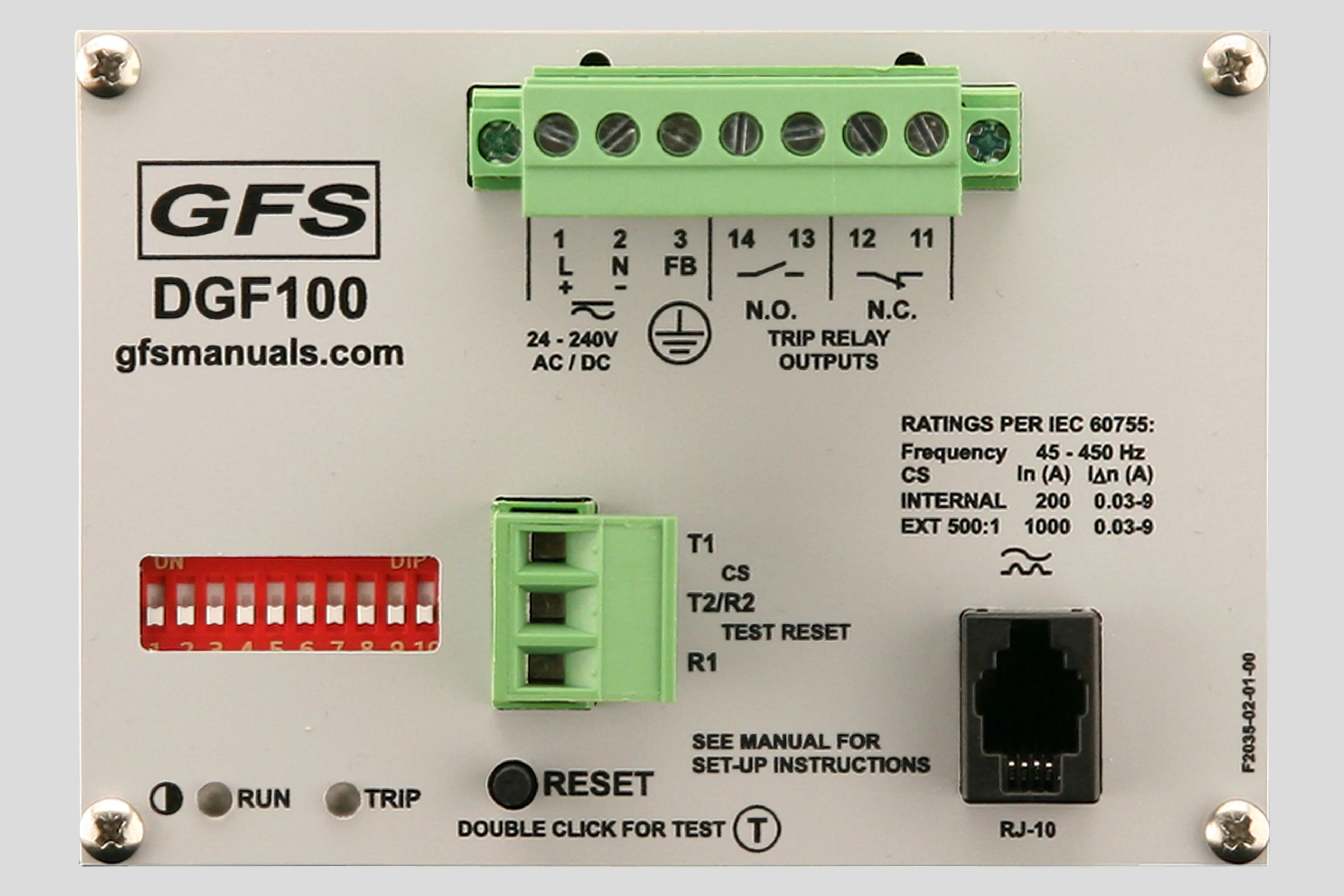
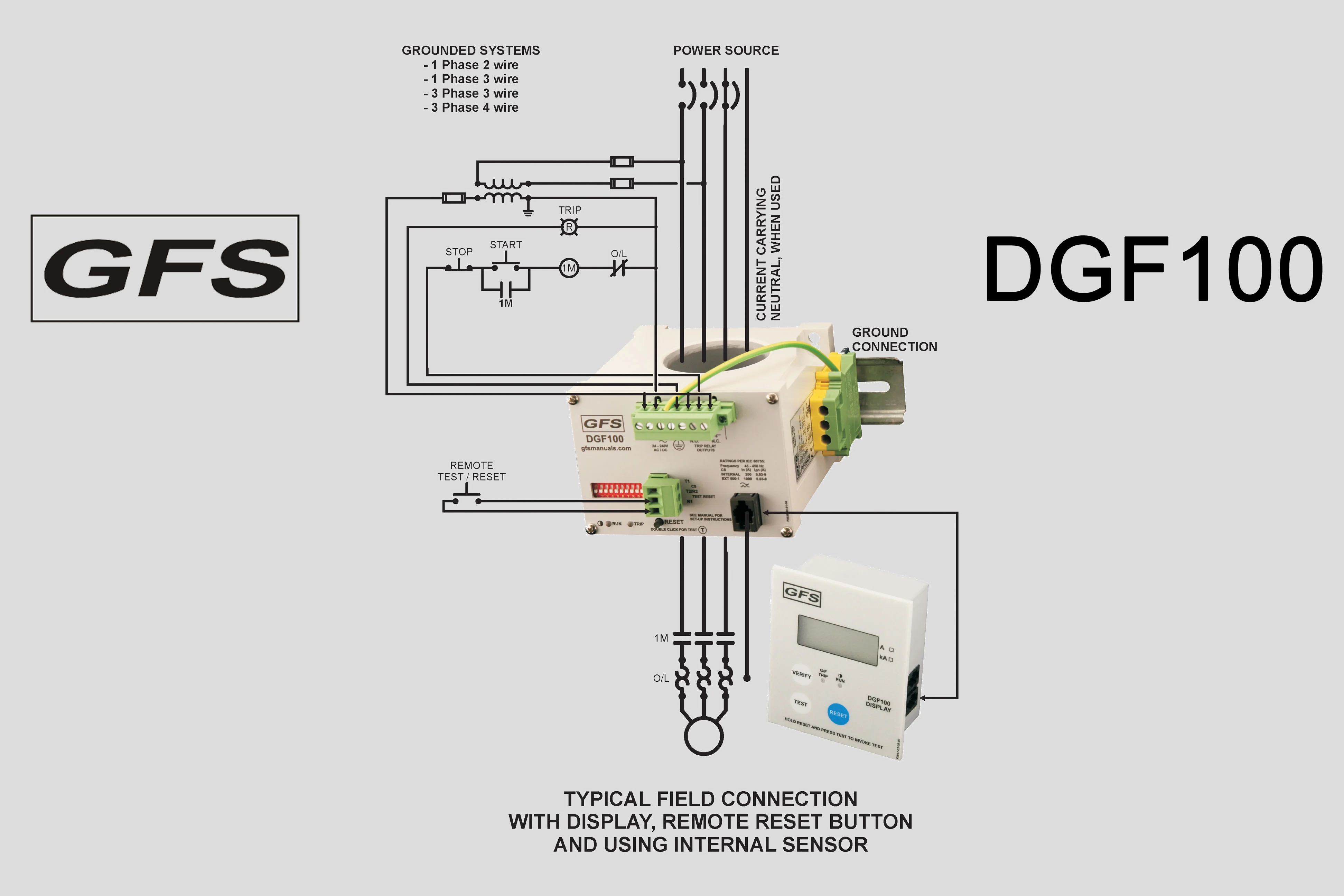
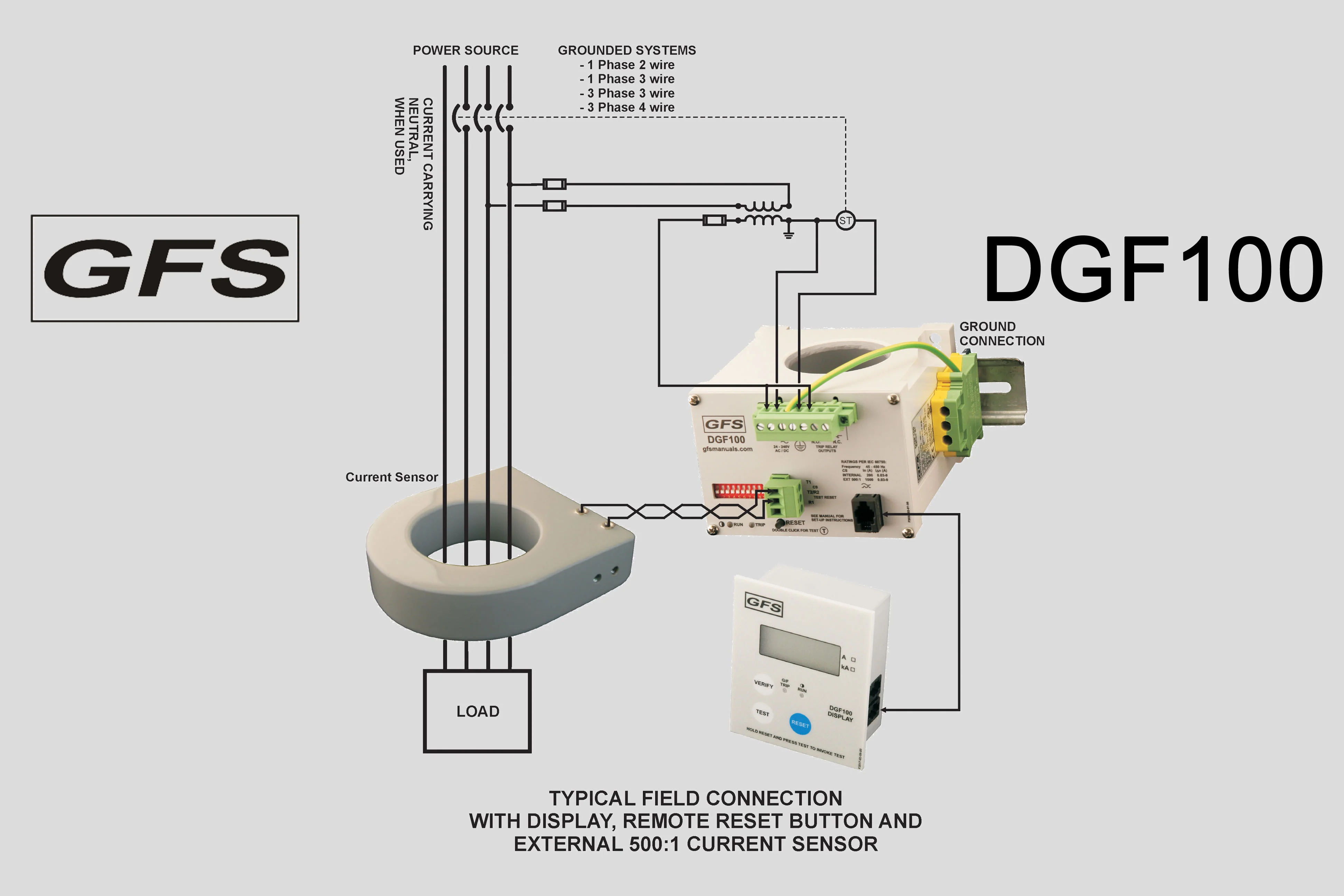
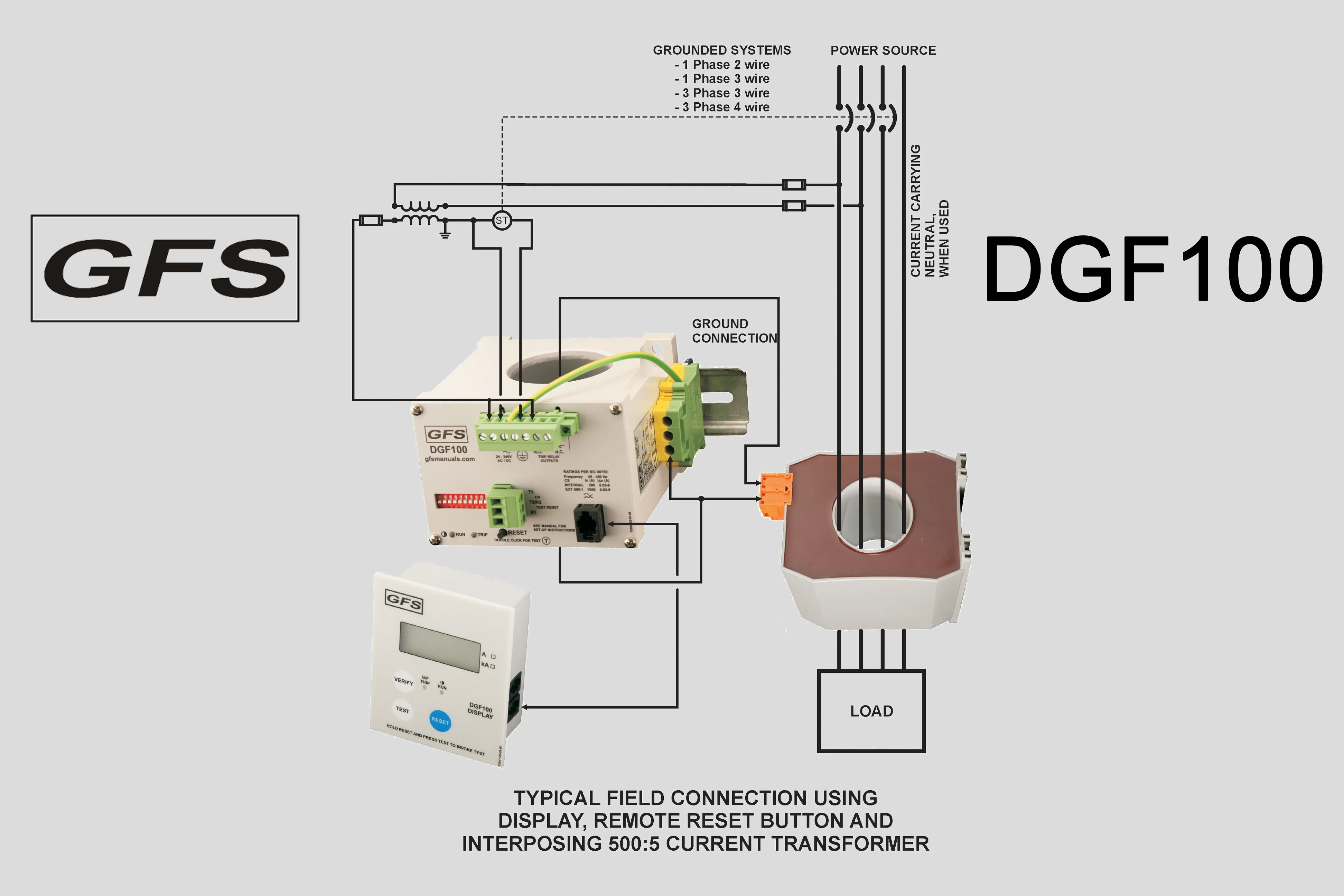
The DGF100 is a microprocessor based ground fault unit for use on solidly grounded or resistance grounded systems. This innovative digital electronic unit measures ground fault current using a built-in 46 mm zero sequence Current Sensor (CS), or an external Current Sensor. (Go to sensors.) External Current Sensors with different cable windows, round or square and split core, and various current ratios are available.
The system will react to alternating current (AC) only and will reject direct current (DC) signals. Accuracy will be maintained over a frequency range of 45 - 450 Hz, making it suitable for variable frequency drive applications. The DGF100 is a Class A device as defined in the IEC 60755 standard; it is therefore fully characterized for operation with sinusoidal AC and pulsating DC currents.
The maximum system operating voltage for the DGF100 is 660 V, when passing the system power conductors through the built-in CS. However, by using any GFS external CS and insulating the busbars, or by using any suitably rated, commercially available, interposing CT and passing the secondary lead through the built-in CS, the relay can be used on any system voltage.
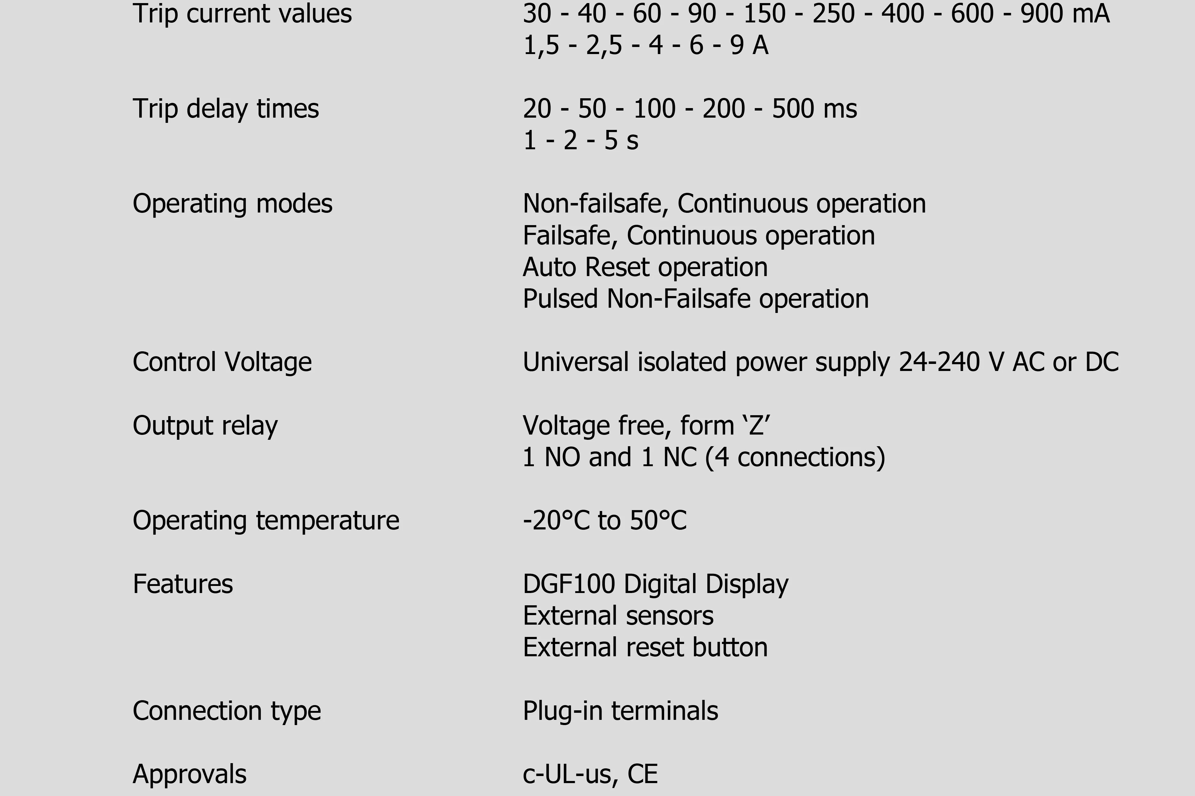
The DGF100 houses an isolated universal power supply from 24 - 240 V AC or DC and is equipped with form ‘Z’ (4 connections) isolated NO and NC contact sets to operate the upstream protection device and to indicate a failure of the system. The Ground Fault (G/ F) Current Trip level (30 mA – 9 A, 14 steps), Trip Delay Time (20 ms – 5 s, 8 steps) and the Relay Operating Mode (Continuous Non-Failsafe, continuous Failsafe, Pulsed Auto Reset and Pulsed Non-Failsafe) are set on a front accessible dipswitch array.
A single press of the ‘RESET’ button, or an external, voltage free, momentary pushbutton resets the relay after a trip. A functional test of the DGF100 is started by either double clicking the cover mounted or external button, or by invoking a test on the DGF100 Display.
For all features, see the manual.
A green ‘RUN’ LED flashes, alternating one second on and off, to indicate that sufficient Control Voltage is applied (Power OK). A red ‘TRIP’ LED indicates that the DGF100 has sensed a Ground Fault and that the output contacts have operated.
7 point and 3 point pull-apart terminal blocks simplify connection of field wiring. A captive screw secures the 7 point block to the relay, safe from the effects of shock and vibration.
A communications port provides access for a remote display. The remote DGF100 Display (see below) shows the actual ground fault current during normal running of the systems. After a trip the ground fault current just prior to the trip is displayed. If the DGF100 Display was connected to the DGF100 at the moment of a trip and the DGF100’s Control Voltage is turned off, pressing the ‘VERIFY’ button will show a red LED indicating a ground fault. If no fault was present the green LED will light.
To ensure that the DGF100 will function in all circumstances, it is encapsulated in polyurethane (PUR) to make sure it is not vulnerable to mechanical shock, vibration nor weather.
DGF100 Display

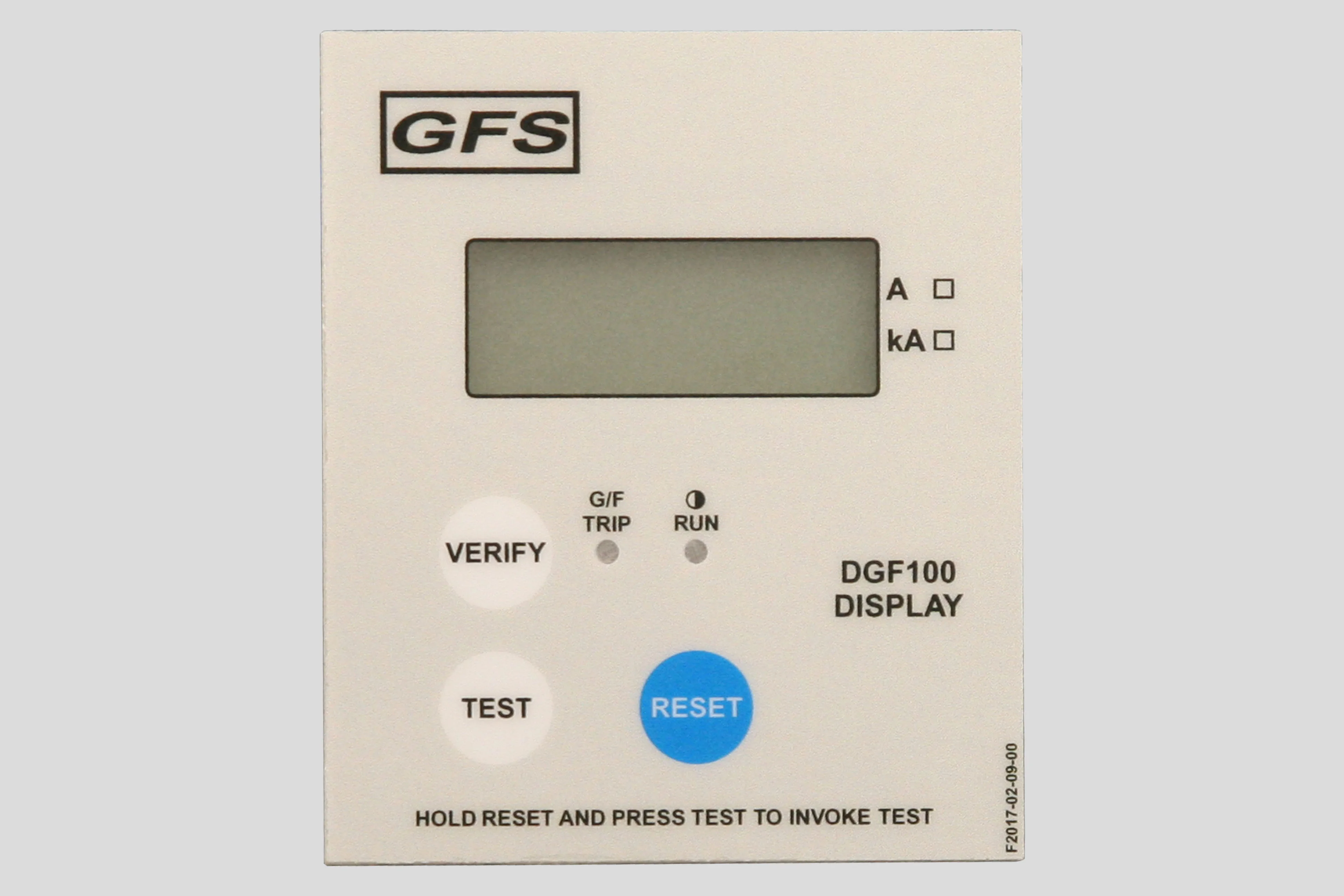

The DGF100 Display is a door mounted, self powered, operator interface to be used in conjunction with
the DGF100 Digital Ground Fault protection unit. It has a four digit LCD panel that normally shows
the magnitude of residual current flowing to ground as it is measured by the DGF100 Ground Fault protection unit.
Three integrated pushbuttons provide a 'TEST', 'RESET' and 'VERIFY' function.
When the DGF100 Ground Fault protection unit loses Control Voltage, pressing the 'VERIFY' button the DGF100
Display will show:
-
A red LED, if the DGF100 tripped due to a ground fault prior to loss of its Control Voltage.
-
A green LED, if there was a loss of power without a ground fault.
A trip of the DGF100 Ground Fault protection unit can be reset by pressing the 'RESET' button on the DGF100
Display.
A test can be invoked on the DGF100 Ground Fault protection unit by using the buttons on the DGF100 Display.
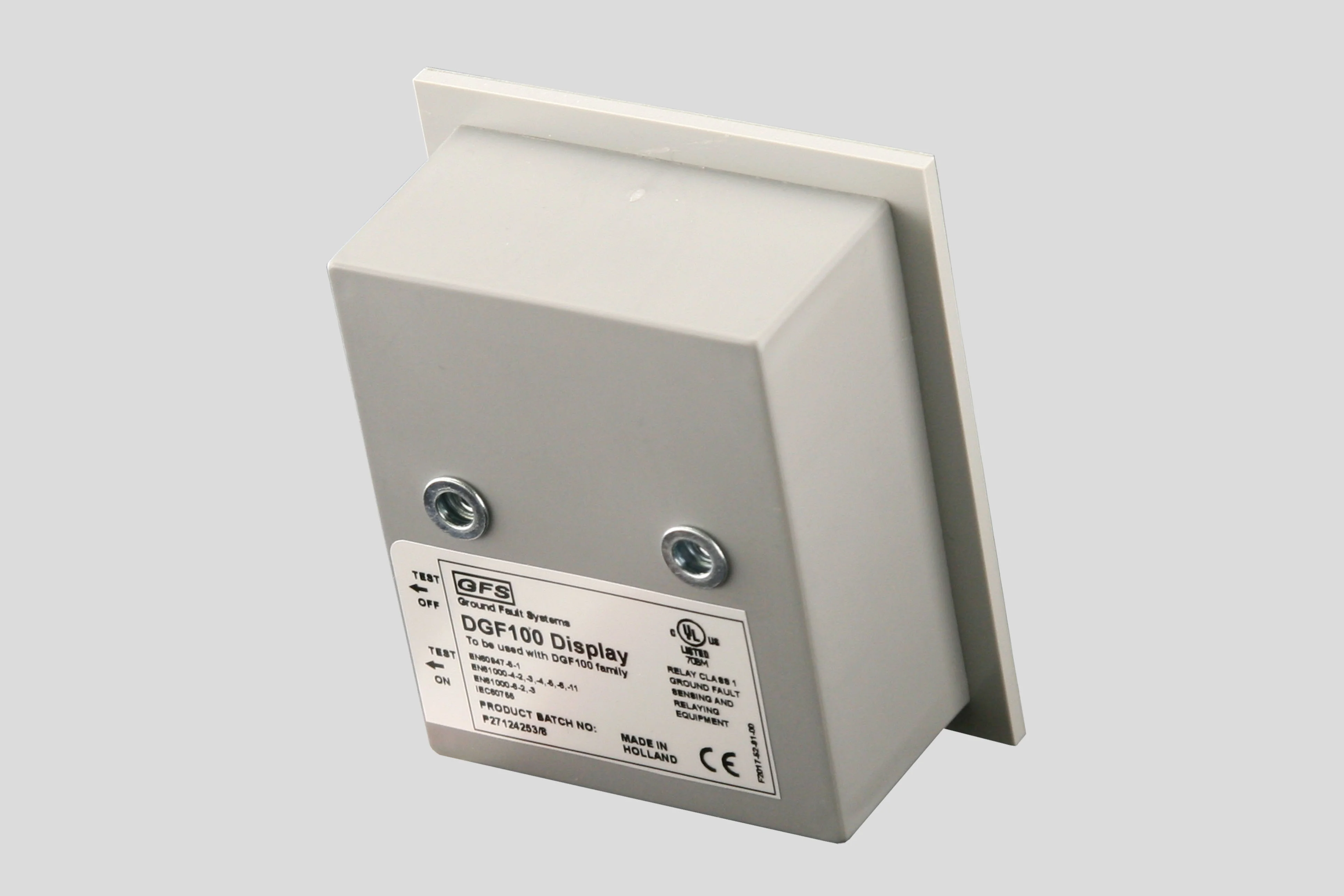
This feature can be enabled/disabled by inserting the interconnecting cable into one of two sockets,
'TEST ON' or 'TEST OFF', on the side of the display.
When the ground fault current exceeds the system's measuring range, the display will show it is out of range.
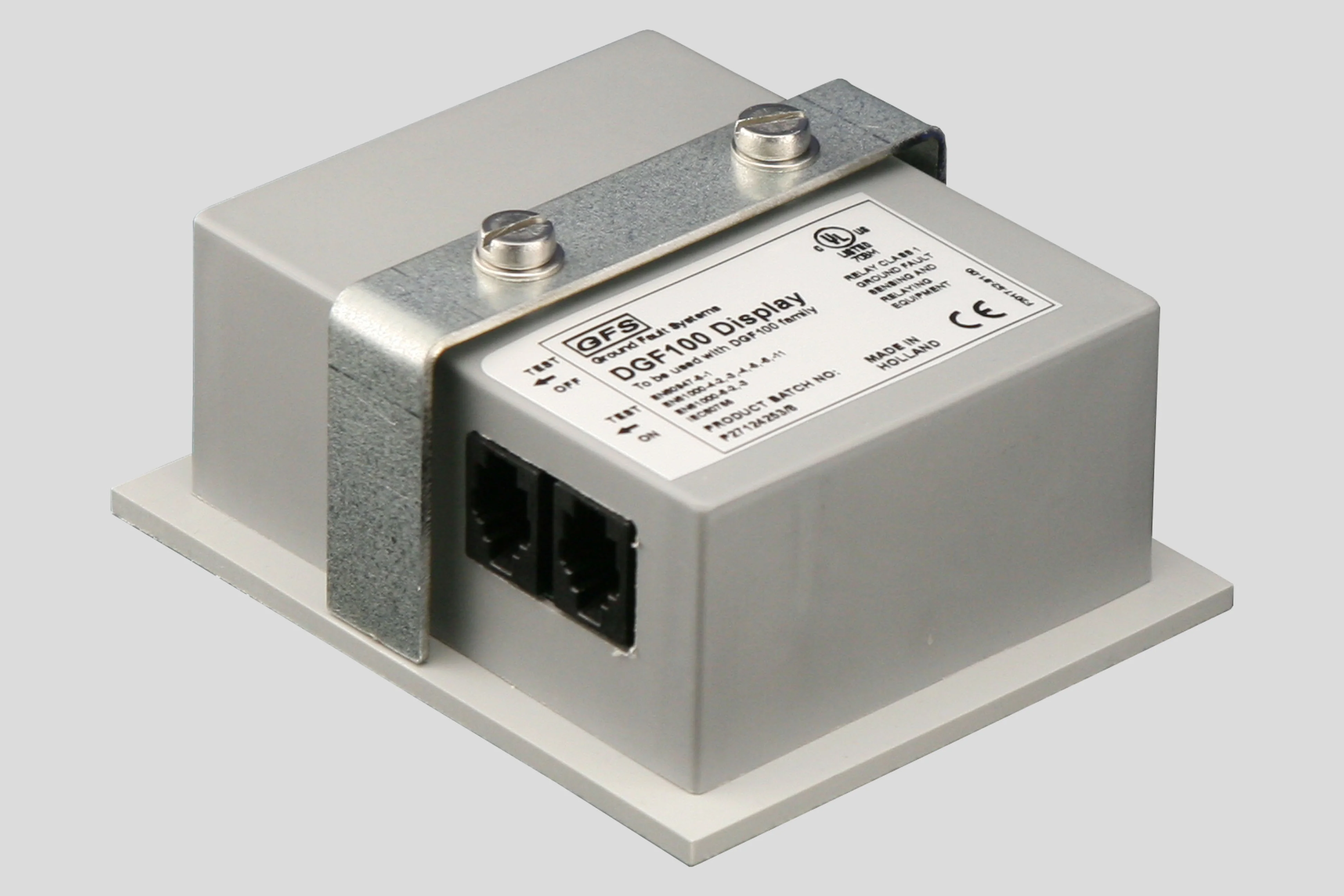
The display is connected to the DGF100 base unit using up to 10 m of RJ-10 type, 4-wire telephone
cable (1 m cable included). No separate power supply is needed.
DGF100 product page

The DGF100 has been brand labelled for Eaton Corp. as the D64RPB100.
The DGF100 is a microprocessor based ground fault unit for use on solidly grounded or resistance grounded systems. This innovative digital electronic unit measures ground fault current using a built-in 46 mm zero sequence Current Sensor (CS), or an external Current Sensor. (Go to Sensors.) External Current Sensors with different cable windows, round or square and split core, and various current ratios are available.
The system will react to alternating current (AC) only and will reject direct current (DC) signals. Accuracy will be maintained over a frequency range of 45 - 450 Hz, making it suitable for variable frequency drive applications. The DGF100 is a Class A device as defined in the IEC 60755 standard; it is therefore fully characterized for operation with sinusoidal AC and pulsating DC currents.
The maximum system operating voltage for the DGF100 is 660 V, when passing the system power conductors through the built-in CS. However, by using any GFS external CS and insulating the busbars, or by using any suitably rated, commercially available, interposing CT and passing the secondary lead through the built-in CS, the relay can be used on any system voltage.
The DGF100 houses an isolated universal power supply from 24 - 240 V AC or DC and is equipped with form ‘Z’ (4 connections) isolated NO and NC contact sets to operate the upstream protection device and to indicate a failure of the system. The Ground Fault (G/ F) Current Trip level (30 mA – 9 A, 14 steps), Trip Delay Time (20 ms – 5 s, 8 steps) and the Relay Operating Mode (Continuous Non-Failsafe, continuous Failsafe, Pulsed Auto Reset and Pulsed Non-Failsafe) are set on a front accessible dipswitch array.
A single press of the ‘RESET’ button, or an external, voltage free, momentary pushbutton resets the relay after a trip. A functional test of the DGF100 is started by either double clicking the cover mounted or external button, or by invoking a test on the DGF100 Display.
For all features, see the manual.
A green ‘RUN’ LED flashes, alternating one second on and off, to indicate that sufficient Control Voltage is applied (Power OK).
A red ‘TRIP’ LED indicates that the DGF100 has sensed a Ground Fault and that the output contacts have
operated.
7 point and 3 point pull-apart terminal blocks simplify connection of field wiring. A captive screw secures the 7 point block to the relay, safe from the effects of shock and vibration.
A communications port provides access for a remote display. The remote DGF100 Display (see below) shows the actual ground fault current during normal running of the systems. After a trip the ground fault current just prior to the trip is displayed. If the DGF100 Display was connected to the DGF100 at the moment of a trip and the DGF100’s Control Voltage is turned off, pressing the ‘VERIFY’ button will show a red LED indicating a ground fault. If no fault was present the green LED will light.
To ensure that the DGF100 will function in all circumstances, it is encapsulated in polyurethane (PUR) to make sure it is not vulnerable to mechanical shock, vibration nor weather.
DGF100 Display

The DGF100 Display is a door mounted, self powered, operator interface to be used in conjunction with the DGF100 Digital Ground Fault protection unit. It has a four digit LCD panel that normally shows the magnitude of residual current flowing to ground as it is measured by the DGF100 Ground Fault protection unit. Three integrated pushbuttons provide a 'TEST', 'RESET' and 'VERIFY' function. When the DGF100 Ground Fault protection unit loses Control Voltage, pressing the 'VERIFY' button the DGF100 Display will show:
-
A red LED, if the DGF100 tripped due to a ground fault prior to loss of its Control Voltage.
-
A green LED, if there was a loss of power without a ground fault.
A trip of the DGF100 Ground Fault protection unit can be reset by pressing the 'RESET' button on the DGF100
Display.
A test can be invoked on the DGF100 Ground Fault protection unit by using the buttons on the DGF100 Display.
This feature can be enabled/disabled by inserting the interconnecting cable into one of two sockets,
'TEST ON' or 'TEST OFF', on the side of the display.
When the ground fault current exceeds the system's measuring range, the display will show it is out of range.
The display is connected to the DGF100 base unit using up to 10 m of RJ-10 type, 4-wire telephone
cable (1 m cable included). No separate power supply is needed.