


DGF7-14 product page


The DGF7-14 has been brand labelled for Eaton Corp. as the D64RP14.
The DGF7-14 is a microprocessor based ground fault unit for use on solidly grounded or resistance grounded systems. This innovative digital electronic unit measures ground fault current using a built-in 28 mm zero sequence Current Sensor (CS), or an external CS. (Go to Sensors.) External CSs with different cable windows, round or square and split core, and various current ratios are available.
The unit will react to alternating current (AC) only and will reject direct current (DC) signals. Accuracy will be maintained over a frequency range of 45 - 450 Hz, making it suitable for variable frequency drive applications. The DGF7-14 is a Class A device as defined in the IEC 60755 standard; it is therefore fully characterized for operation with sinusoidal AC and pulsating DC currents.
The DGF7-14 is designed for use with Neutral Grounding Resistors (NGR) having let-through current between 2 and 10 A.
The maximum system operating voltage for the DGF7-14 is 660 V, when passing the system power conductors through the built-in CS. However, by using any GFS external CS and insulating the busbars, or by using any suitably rated, commercially available, interposing CT and passing the secondary lead through the built-in CS, the unit can be used on any system voltage.
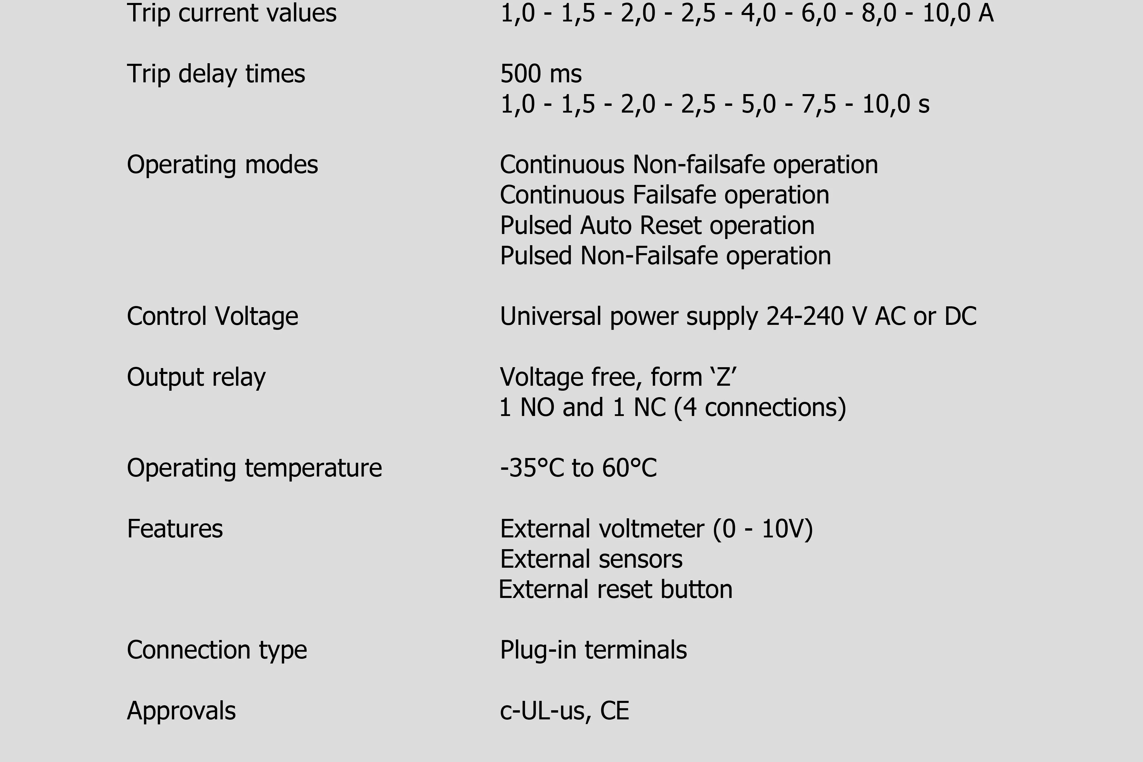
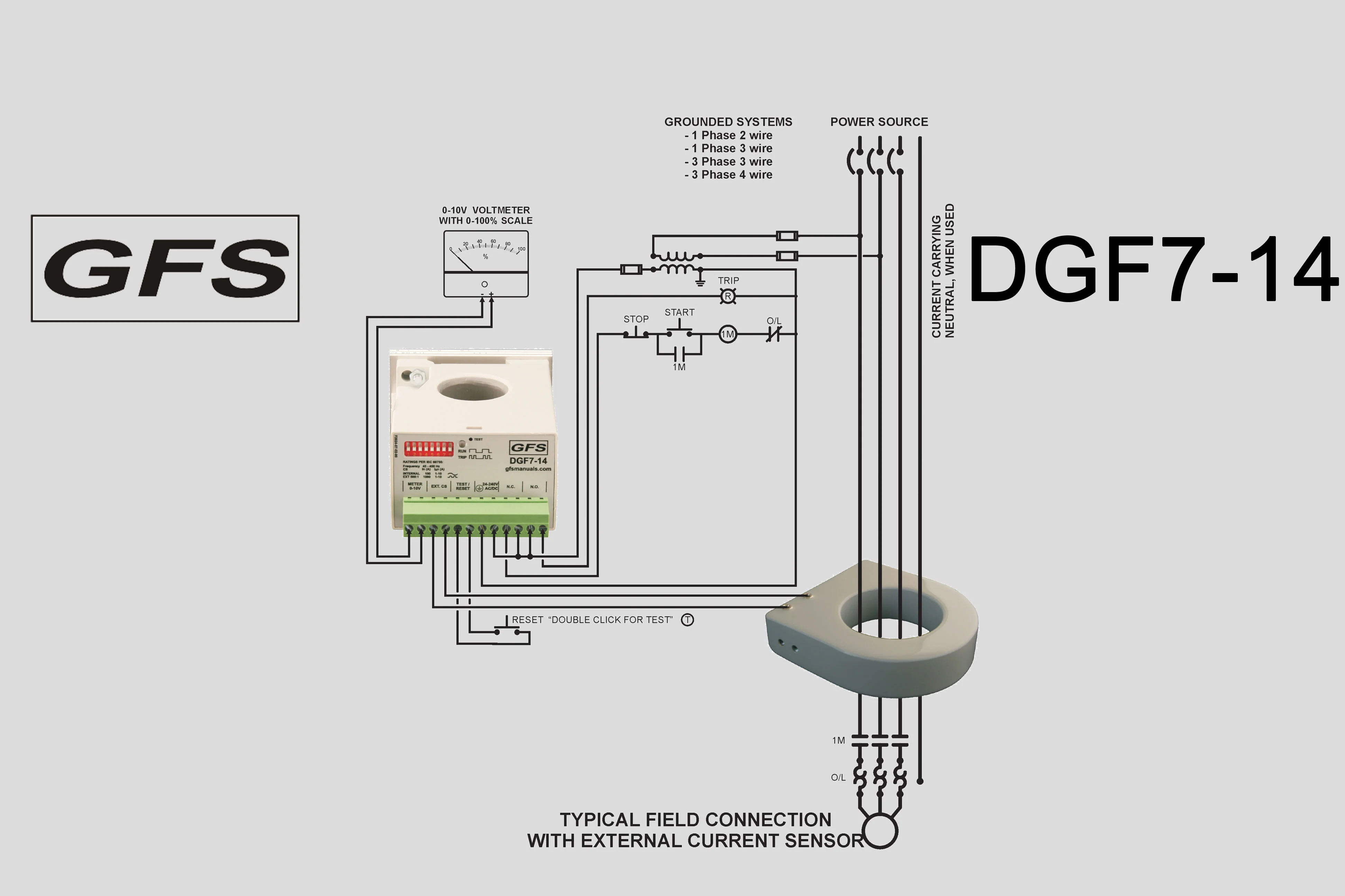
The DGF7-14 houses a non-isolated universal power supply from 24 - 240 V AC or DC and is equipped with form ‘Z’ (4 connections) isolated NO and NC contact sets to operate the upstream protection device and to indicate a failure of the system. The Ground Fault Current Trip level (1 – 10 A, 8 steps), Trip Delay Time (500 ms – 10 s, 8 steps) and the Relay Operating Mode (Continuous Non-Failsafe, Continuous Failsafe, Pulsed Auto Reset, Pulsed Non-Failsafe) are set on a front accessible dipswitch array.
A single press of an external, voltage free, momentary button resets the unit after a trip. A functional test of the DGF7-14 is started by double clicking the external button.
A green LED indicates four functions: slow flashes denote Control Voltage is present (1 s flashes); steady on after a test was invoked, during delay before test continuous flashes (0,25 s); two fast flashes per second denotes the unit has sensed a ground fault current higher than the Trip Level for a period longer than the Trip Delay Time and that the output contacts have operated (two 0,25 s flashes).
A 12 point Pull-apart terminal block simplifies connection of field wiring.
Terminals are provided for connection of an external voltmeter. The output is 0 to 10 V, proportional to the Trip Current Level set on the dipswitches.
The DGF7-14 is equipped with an aluminium profile enabling horizontal mounting on a DIN rail.
To ensure that the DGF7-14 will function in severe circumstances, it is encapsulated in polyurethane (PUR) to make sure it is not vulnerable to mechanical shock, vibration nor weather.
DGF7-14 product page

price:€
In stock:
The DGF7-14 has been brand labelled for Eaton Corp. as the D64RP14.
The DGF7-14 is a microprocessor based ground fault unit for use on solidly grounded or resistance grounded systems. This innovative digital electronic unit measures ground fault current using a built-in 28 mm zero sequence Current Sensor (CS), or an external CS. (Go to Sensors.)External CSs with different cable windows, round or square and split core, and various current ratios are available.
The unit will react to alternating current (AC) only and will reject direct current (DC) signals. Accuracy will be maintained over a frequency range of 45 - 450 Hz, making it suitable for variable frequency drive applications. The DGF7-14 is a Class A device as defined in the IEC 60755 standard; it is therefore fully characterized for operation with sinusoidal AC and pulsating DC currents.
The DGF7-14 is designed for use with Neutral Grounding Resistors (NGR) having let-through current between 2 and 10 A.
The maximum system operating voltage for the DGF7-14 is 660 V, when passing the system power conductors through the built-in CS. However, by using any GFS external CS and insulating the busbars, or by using any suitably rated, commercially available, interposing CT and passing the secondary lead through the built-in CS, the unit can be used on any system voltage.
The DGF7-14 houses a non-isolated universal power supply from 24 - 240 V AC or DC and is equipped with form ‘Z’ (4 connections) isolated NO and NC contact sets to operate the upstream protection device and to indicate a failure of the system. The Ground Fault Current Trip level (1 – 10 A, 8 steps), Trip Delay Time (500 ms – 10 s, 8 steps) and the Relay Operating Mode (Continuous Non-Failsafe, Continuous Failsafe, Pulsed Auto Reset, Pulsed Non-Failsafe) are set on a front accessible dipswitch array.
A single press of an external, voltage free, momentary button resets the unit after a trip. A functional test of the DGF7-14 is started by double clicking the external button.
A green LED indicates four functions: slow flashes denote Control Voltage is present (1 s flashes); steady on after a test was invoked, during delay before test continuous flashes (0,25 s); two fast flashes per second denotes the unit has sensed a ground fault current higher than the Trip Level for a period longer than the Trip Delay Time and that the output contacts have operated (two 0,25 s flashes).
A 12 point Pull-apart terminal block simplifies connection of field wiring.
Terminals are provided for connection of an external voltmeter. The output is 0 to 10 V, proportional to the Trip Current Level set on the dipswitches.
The DGF7-14 is equipped with an aluminium profile enabling horizontal mounting on a DIN rail.
To ensure that the DGF7-14 will function in severe circumstances, it is encapsulated in polyurethane (PUR) to make sure it is not vulnerable to mechanical shock, vibration nor weather.